SOLIDWORKS, Part 9

Greetings again fine folks!

Here is the compressor to be housed in the turbo.


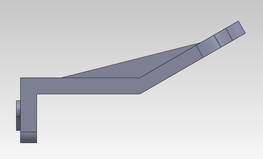
The primary features used in constructing this are the Loft, Circular Pattern, Revolve Cut, and Revolve features. As you can see the compressor fins are constructed using two rectangles offset above each other and at an angle to each other. Then a 3D Sketch is created to create the curvature along the path that intersects them. The Spline sketch tool is used to accomplish this. The bottom fin is constructed in a similar manner. Once the two fins are completed we use the Circular Pattern feature to created the circular array of fins centered across the central axis. 

Impellers are designed like this in order to suck air from the top and force them down the curvature of the fins into the turbo volute. When spooling it can achieve from anywhere to 80,000 to 200,000 rpm, creating significant amounts of pressure. 


1060 Aluminum Alloy is designated to the part and a final rendering is done. 


SOLIDWORKS, Part 8

Greetings everyone!

For this turbo housing we have used most of the features we have previously discussed, along with the Loft feature complemented with a sketch using 3D Sketch.


This turbo was made by using the Loft Feature, along a tapering cylindrical helix. I will cover more on how to accomplish this later because it can be a little daunting, especially if you are new to using the Loft Feature. 

From here the taper is clearly visible. 

Above is a section view of the turbo using the Top Plane. This main housing is used to house the turbo compressor or impeller, if you will. We have assigned '1060 Aluminum Alloy' to the turbo and used Photoview 360 to accomplish a final rendering. 


Notice how there is debossed text on the output of the turbo volute. This is useful to imprint company logos and model types. We will cover more of how this is accomplished later. 


SOLIDWORKS, Part 7

Greetings again folks!

Here is another part using most of the features we have discussed so far. 


To construct this part we have implemented most of the our basic features. An important aspect of constructing this part is the Mirror feature, which was used to construct the 'wings' which contain the handle, as it were. Using the Mirror feature saves a lot of time and hassle and is truly one of SolidWorks most indispensable features. 

To construct the handlebar that spans across the 'wings', we made a reference plane that cut through the middle of the drawing and sketched our circle. Subsequently, we used the Extrude feature to extrude it in two different directions. In the Extrude Property Manager, for both directions, we select Extrude to Surface, so that our extrusion does not overlap the material. 

Now for this specific part I decided to assign a material to it. I decided to go with Chrome Stainless Steel. You can easily assign material to any of your parts by right clicking in Materials under the Annotations folder in the Feature Manager Design Tree, and clicking Edit Material. You can choose any material from the various choices and select apply to designate it to your part. 


With the material applied, if you have the Photoview 360 add-on, you can select Final Render, from the Photoview 360 Menu found on your menu bar, to view a nice smooth final rendering of your part with applied material. 
 

SOLIDWORKS, Part 6

Hello folks!

Here is another part example with several key SolidWorks features implemented into the design.

Aside from the Rib, Extrude, and Extrude Cut features, we have also used the Linear Sketch Pattern and Circular Sketch Pattern, to sketch the holes on the base and top respectively.  Notice that we have also used another Reference Plane to construct the top portion of the part.


Here we can see it from the top view port. 


SOLIDWORKS, Part 5

Hello ladies and gentlemen!

In this example part, we have used a combination of several of the features previously covered in order to start fabricating a little more complex part.


This part was made by using the Revolve feature in order to revolve a base 2D Sketch. Once that was done we have used a Reference Plane and Extrude Thin, in order to extrude the smaller cylindrical section towards the main body at a arbitrary angle. 

We also toggled with the various options in the Extrude Property Manager, which displays once you activate the Extrude Feature, in order to extrude the body at the bottom of the cylindrical surface towards the main section of the body without extruding past the surface. 


SOLIDWORKS, Part 4

Hello again everybody!

Here is another example of using Reference Planes, to construct at an angle with respect to another body.

Sometimes Reference Planes can be a little tricky, especially if you would like it both offset and at an angle from another reference point. We will cover more of that later.


As you can see from the above Isometric view point. We have used the powerful Shell feature in order to shell the inside of an original extrusion made from a simple rectangle. This is easily accomplished by selecting "Shell", from the Features Toolbar, and simply selecting the top surface of the rectangle and specifying the Shell thickness.

SOLIDWORKS, Part 3

Greetings Everyone!

Yet again, for this part we have utilized the Rib feature. We have also used a Reference Plane to construct part of the body at an angle with respect to the base.

You can view this angle better from viewing it from the right as as so.


SOLIDWORKS, Part 2

Hello Everyone!

Here is another part utilizing a few more features. As you can see we have made a rib using the Rib feature. We have also used the Revolve feature to construct the edge around the extruded circle cut seen on the top surface of the part.

Here is another look from a different perspective.

We have also used the Fillet feature to smooth out the sharp edges. 

SOLIDWORKS, Part Example 1

Greetings folks!

I will post more tutorials later as soon as I have a little bit more time. For now, throughout the next few posts I will display a vast array of different parts in order to emphasize the power of SolidWorks and its various capabilities made possible by the use of several key features. So here is a basic part using a few of the fundamental features such as Circular Sketch Patterns, and Extrude feature.


As you can see, we have sketched slots on the front face in order to extrude it to the bottom surface. This is more apparent when you view it normal to the front face.